Door Wiring Issues
Hire a professional. One that knows how to operate a multi-meter.
The Keys work but the state of the lock does not change. (Door does not unlock)
- It's important to confirm the correct door is wired to the correct relay.
- There is an indicator light next to the relay that can be checked the correct relay is triggered.
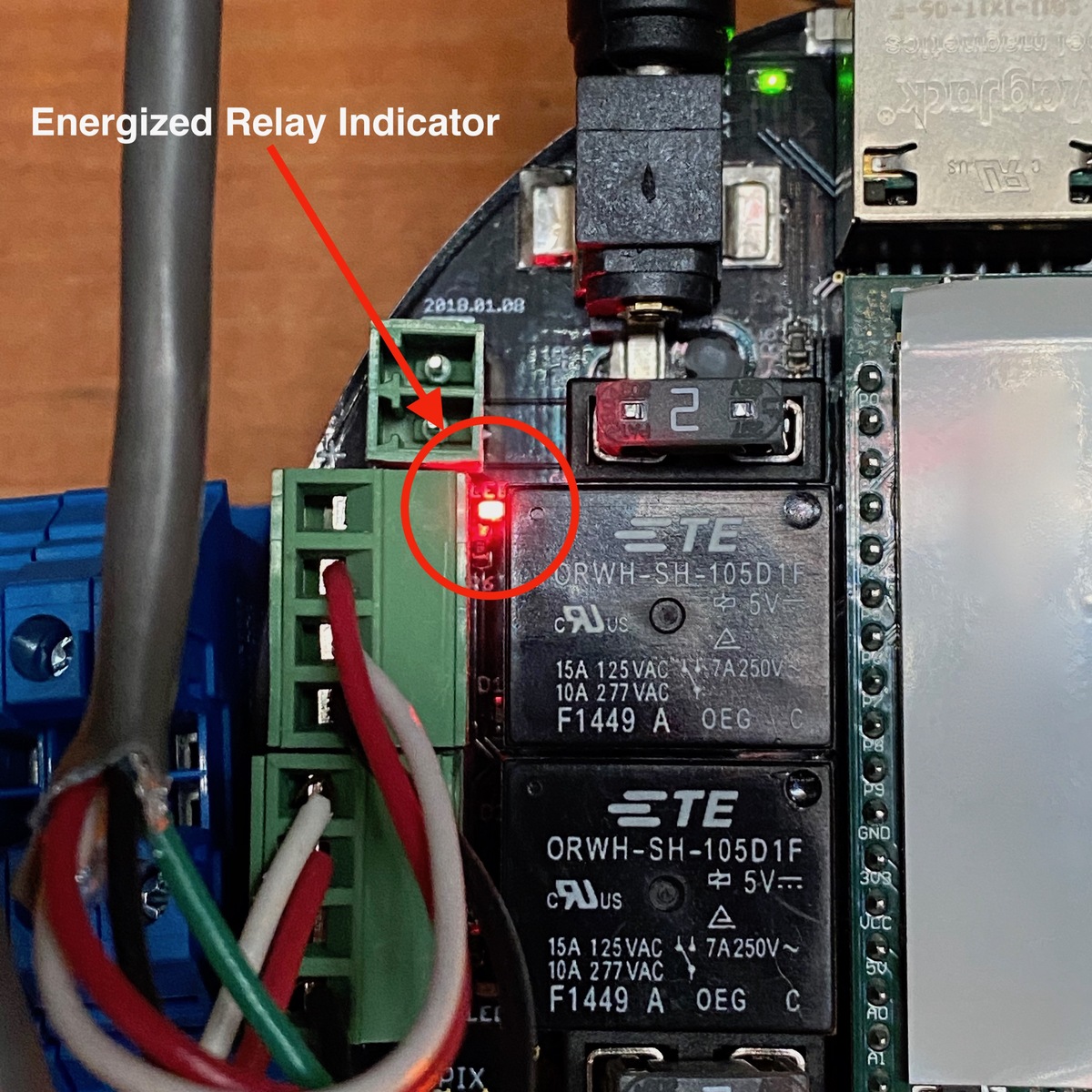
- When the key is pressed you should be able to hear a faint "click" and the indicator light will illuminate for the duration of the lock being unlocked.
- If the door is wired to the correct relay and the indicator light illuminates but the door still does not unlock the next item to check is the fuse.
- A fuse will only be present if the Proximity Open Controller is wired to send power to the lock. If the Proximity Open Controller is wired to be a "Dry Contact" or "Piggyback" there will be no fuse present.
- There will be a dedicated fuse for each of the four relays. Pull the correct fuse and check if the fuse is still good.
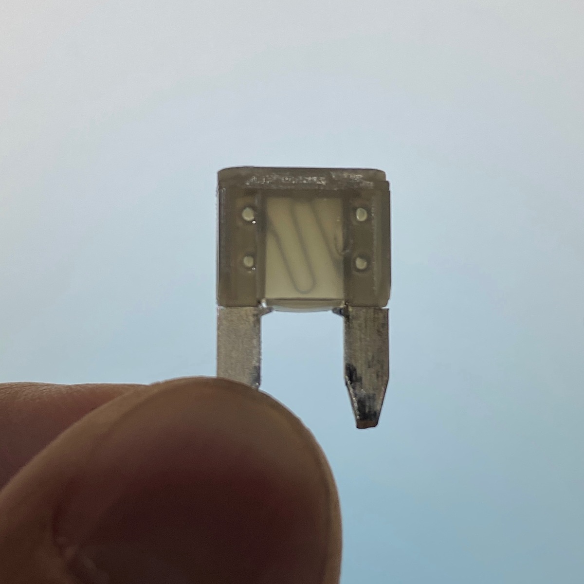 Good Fuse
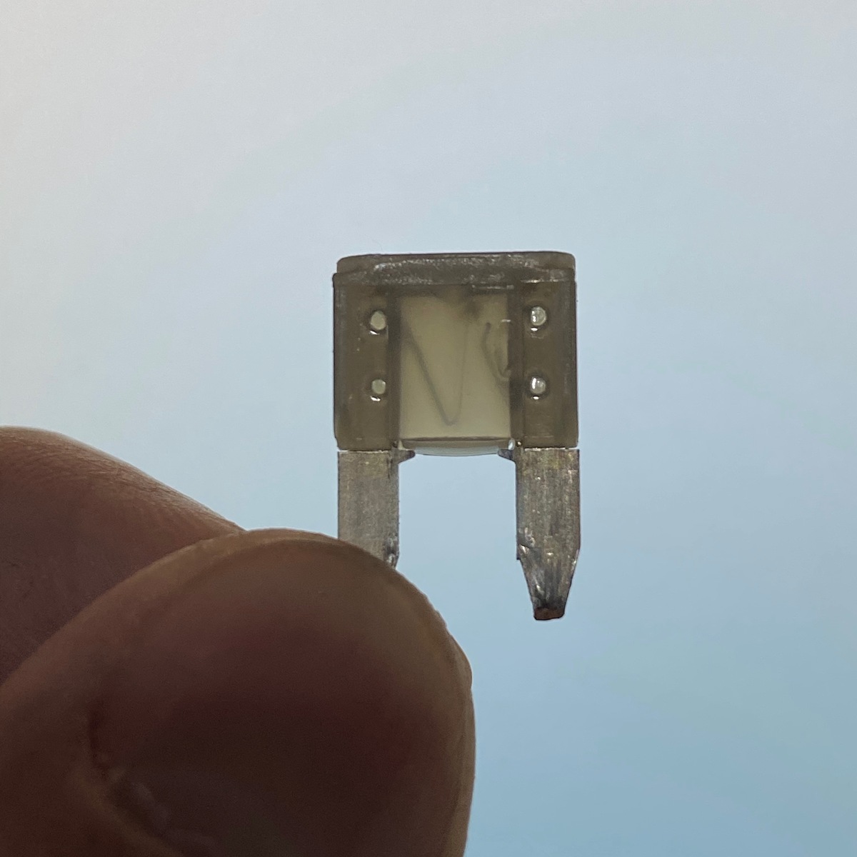 Blown Fuse (Notice the break in the wire through the clear part of the fuse)
- If the fuse is blown it will need to be replaced with a 2 Amp Mini Blade Fuse.
- If the fuse is blown there is also most likely a wiring issue. The fuse will blow when the circuit is short circuited.
- Refer to the PDF wiring diagram to correct the issue.
- If the fuse is good and the door still does not unlock a multimeter will be needed to troubleshoot further. This step is only useful when the Proximity Open Controller is wired to send power to the lock. "Dry Contact" or "Piggyback" will require different testing.
- A qualified professional should be using a multimeter to check voltage coming from the Proximity Open Controller.
- If the lock in question is a magnet place the multimeter electrodes on the GND (Ground) and NC (Normally Closed) terminals of which ever channel is being tested.
- In an "Locked" state a magnet should be getting 12VDC or 24VDC of power, depending on the voltage requirements of the lock and power supply in place.
- In an "Unlocked" state a magnet should not be getting any power. The multimeter should read 0.
- If the lock in question is a strike place the multimeter electrodes on the GND (Ground) and NO (Normally Open) terminals of which ever channel is being tested.
- In an "Locked" state a strike should not be getting any power. The multimeter should read 0.
- In an "Unlocked" state a strike should be getting 12VDC or 24VDC of power, depending on the voltage requirements of the lock and power supply in place.